0% Loading Lightning Risk Assessment…

IEC / BS EN 62305-2 working reference

Assessment Parameters & Instruction Manual

Use this guide to collect defensible inputs, complete the app in the correct order, and quality-check the generated report.

Report input register

Parameters that materially affect the assessment

Confirm these values from drawings, the client questionnaire, lightning data, equipment schedules, and approved design information before issuing the report.

Acceptance rule For IEC 62305-2:2024, compare the calculated risk R with tolerable risk RT, normally 1E-5/year unless a different criterion is justified. Where internal-system availability matters, also compare F with FT: typically 0.1/year for critical systems or 1/year for non-critical systems.
01

Project basis and scope

Defines what the report covers.

Identity
Project, client, location, document number, date, revision, prepared and verified by.
Standard edition
Select the contractually required IEC or BS EN 62305-2 profile before entering risk data.
Assessment scope
Structure, connected services, internal systems, zones, adjacent structures, exclusions, and interfaces.
Risk applicability
State why each available risk category is included or excluded; identify any genuine public service or cultural value.
02

Lightning and environment

Controls the number of dangerous events.

NSG / Ng
Ground flash or strike-point density in flashes/km²/year. Record the data source, map/provider, location, and date.
k
Lightning-location-system provider factor. For IEC 2024, document the provider value; use 2 only as an explicit fallback assumption when unavailable.
CE
Environmental factor: rural 1, suburban 0.5, urban 0.1, or urban with buildings over 20 m 0.01.
Thunderstorm days
Use only when the selected workflow derives lightning density from keraunic data; retain the stated source and conversion basis.
03

Structure geometry and location

Sets the structure collection area.

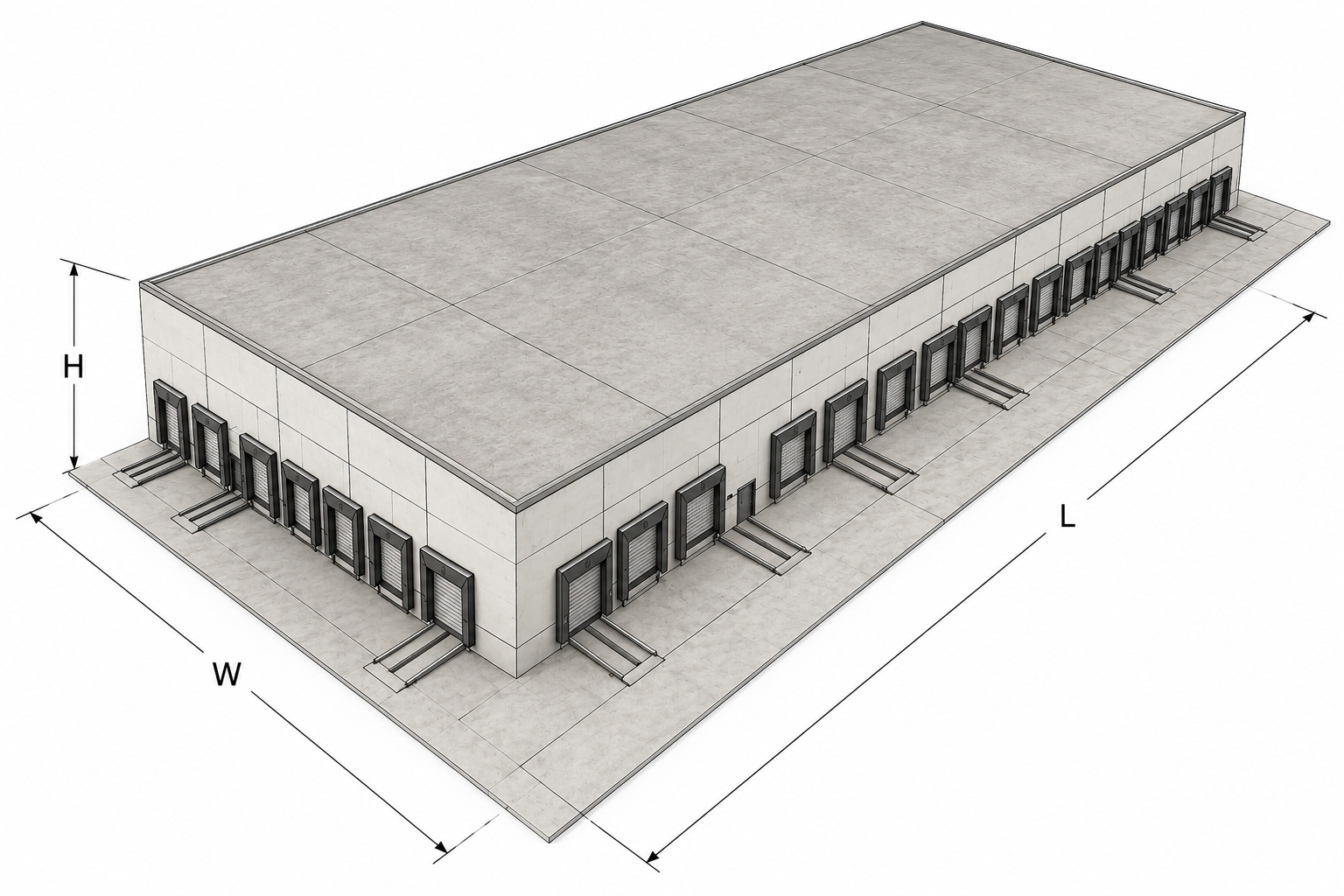
L, W, H
Maximum length, width, and height in metres, including relevant roof projections and exposed high points.
Shape / collection area
Select the representative geometry or enter the known collection area for a complex structure. Verify AD and AM.
CD
Location factor: higher surrounding objects 0.25; same/lower objects 0.5; isolated 1; hilltop/knoll 2.
Adjacent structure
Record connected adjacent geometry, location factor CDJ, transformer/interface factor, and whether it can introduce risk through a service.
04

Incoming lines

Usually the most assumption-sensitive input group.

LL
Length of each power, telecom, data, or metallic service section. Split sections when routing, shielding, grounding, isolation, or environment changes.
CI
Installation factor: aerial 1, buried 0.3, or buried fully within meshed earth termination 0.01.
CT
Line type factor: normally 1; use 0.2 for HV supplied through a transformer with separated windings.
CLD, CLI
Direct/near-line coupling factors based on line shielding and bonding. Confirm whether the shield is bonded to the same equipotential bar.
UW, RS
Equipment impulse withstand voltage and cable-shield resistance; obtain these from equipment and cable data, not generic assumptions where records exist.
05

Zones, occupancy, and exposure

Connects physical areas to probability and loss.

Zone definition
Separate zones when floor/soil, fire compartment, shielding, internal systems, occupancy, protection, or loss consequence changes.
tz
Hours per year that persons are present in the dangerous place; verify realistic occupancy and avoid exceeding 8760 hours.
te
Hours per year that equipment is exposed or required for the assessed service.
rt
Surface factor: concrete/agricultural 1E-2, marble/ceramic 1E-3, gravel/carpet 1E-4, asphalt/linoleum/wood 1E-5.
People and values
Record persons in zone and total persons, plus cultural/economic values only for selected applicable risks.
06

Fire, explosion, and loss

Fire and explosion risk often dominates the consequence term.

rf
Fire/explosion factor: explosion Zone 0/20 1, Zone 1/21 1E-1, Zone 2/22 1E-3; fire high 1E-1, ordinary 1E-2, low 1E-3.
rp
Fire-provision factor: none 1, manual provisions 0.5, automatic extinguishing/alarm 0.2.
Loss factors
Confirm touch/direct injury, physical damage, internal-system failure, service, cultural, economic, and external/environmental loss inputs for each zone.
Evidence
Support the selected fire class, hazardous-area classification, alarm/suppression provision, and loss class with client or design documentation.
07

Protection measures

Use installed or committed measures only.

PLPS / PB
No LPS 1; Class IV 0.2; III 0.1; II 0.05; I 0.02; enhanced natural-metallic arrangements require specific justification.
PEB
Service-entrance bonding/SPD: none 1; LPL III–IV 0.05; LPL II 0.02; LPL I 0.01.
PSPD
Coordinated SPD probability selected from the applicable standard table and equipment/installation design.
KS1–KS3
Shielding and internal wiring/routing factors. Unshielded routing ranges from 1 to 0.01; shielded cable or bonded metal conduit may use 0.0001 where justified.
TWS / access controls
Count warning, evacuation, disconnection, or access measures only when procedures make them effective and auditable.
08

Key outputs to review

Checks before accepting the result.

Dangerous events
Review ND, NDJ, NM, NL, and NI against the entered geometry and services.
Risk components
Each component follows RX = NX × PX × LX. Investigate dominant components rather than only the total.
Pass/fail
Confirm the selected risks meet their tolerable criteria both before and after proposed protection.
Traceability
Every non-default value and exclusion should be traceable to a drawing, schedule, survey, client confirmation, standard table, or approved assumption.
Use of typical values Values shown here are report-working references, not automatic design selections. Always confirm the selected edition, applicable national values, project evidence, and engineering justification before issue.